+86-13914052243
Aimed at the processing problems of the fluid channel (also known as the internal curved hole) in the large flange end cover, the key component in the aviation equipment field such as centrifugal compressor and air separation compressor and its processing and manufacturing equipment. An EDM forming method for internal fluid channels is proposed. The realization structure of a flexible transmission device for EDM of internal fluid channels is studied. The bending avoidance structure, insulation and chip removal structure, and internal fluid channel EDM are developed. The process technology solves the problems that the traditional processing method has many procedures and high costs, and the opening of auxiliary holes affects the life of the parts and is easy to crack, which causes the leakage of toxic liquid and increases the potential safety hazards. The diameter of the processed internal fluid channel can reach 15-20mm, the coplanarity between the two ends of the test sample and the internal fluid channel is ≤0.8mm, and the butt joint is smoothly transitioned, and the surface roughness Ra≤3.2μm, which can realize the interior with various tilt angles The processing of fluid channels provides an effective method for the design and manufacture of similar structural parts in various fields.
With the development of my country's aviation technology, the application of difficult-to-machine materials and complex surface parts is becoming more and more extensive. For example, power plants such as centrifugal compressors and air separation compressors are key components of aviation equipment and related manufacturing equipment, and their operating conditions (such as high pressure, toxic, harmful, corrosive, etc.), energy efficiency and conversion Efficiency is getting higher and higher, environmental protection and safety requirements are getting stricter. The material of this kind of parts has a high viscosity, high hardness, extremely complicated spatial shape, and difficult cutting process, which has become a "bottleneck" in manufacturing. EDM technology has become an indispensable processing method for the above-mentioned difficult-to-machine parts due to its remarkable characteristics such as no cutting force machining and no tool mark machining. The large flange end cover is a key component in this type of device. It not only plays the role of fixed support and sealing but more importantly, various liquid or gas paths are arranged on it to act as a transmission medium. Figure 1 is a schematic diagram of this kind of part.

The structural characteristics of this kind of parts are large size and heavyweight: the diameter is greater than 1m, and the weight is greater than 1 ton; the diameter of the inner fluid channel processing hole is small: generally ϕ15~20mm; the material is special: mostly precipitation hardening corrosion-resistant stainless steel, nickel-chromium iron alloy, high-strength stainless steel, and other difficult-to-process materials.
The traditional manufacturing method, whether it is a CNC EDM drill machine or EDM machine, generally can only process the square hole that communicates with the outside first, and then the square hole that is connected to the outside is blocked and welded with a plugging post. Figure 1 shows that the outside is processed first the 3, 5 holes, and then plug the excess external holes of holes 3 and 5 with plugs 1 and 4, and then welds the plugs and other processes.
This method first increases the manufacturing and testing procedures, increases the cost, and the more open holes affect the strength and rigidity of the parts and reduce the service life; the second is that the sealing part is easy to crack and corrode, causing the leakage of toxic gas. Increased security risks. Therefore, the effective way to solve this problem is to directly process the internal fluid channels. However, due to the internal structure of the liquid and air holes, the traditional machining methods cannot achieve processing due to the interference of the tools, which has become a technical bottleneck.
At present, the curved hole machining technology is highly valued by many scholars, and the research on the curved hole EDM technology and application has been carried out, such as the use of wire hanging electrodes to process curved holes, the use of SMA functional materials and bionic technology to develop curved holes. The spark machining robot uses the principle of the mouse to make holes for electric spark machining. This paper proposes another EDM method suitable for internal fluid channels in the processing area. This method is mainly composed of four parts: flexible transmission device, bending avoidance structure, insulation and chip removal structure, and electrical Spark Erosion Machining process technology.
1. Flexible transmission device
In order to realize the electric discharge machining of the internal fluid channel, the turning of the tool electrode in the part and the turning accuracy control problem must be solved first. For this reason, this paper designs a method of using the external vertical hole (a straight hole or oblique hole) that has been machined on the part. The structure of the flexible transmission device that realizes the horizontal hole processing at a certain set angle with the vertical hole is shown in Figure 2. It is mainly composed of tool electrode transfer assembly, positioning bushing, and positioning guide devices. It has a three-dimensional controllable transmission structure and is the most important part to realize the EDM of the internal fluid channel.
Working principle of a flexible transmission device:
(1) First use machining or EDM to machine the external vertical hole, and then insert the device into the bottom of the hole. In order to align the tool electrode to the required processing position when inserting the device, mill a flat surface at the corresponding position on the device for easy use The wrench adjusts the direction of the tool electrode movement path; then tighten the fixing screw on the reference positioning block to clamp the left positioning sleeve, and finally fix the device and the workpiece together. In order not to damage the surface of the part, and without adding a special bracket, a fixed magnet can be used to attract the reference positioning clamp block and the workpiece together, so that the fixing of the device and the determination of the direction of the processing hole are completed.

(2) Fix the tool electrode conveyor belt with the main shaft of the CNC EDM machine tool, and use the servo motion of the main shaft to realize the movement of the electrode forward and backward; the positioning shaft sleeve is a cylindrical rod, and the left positioning shaft sleeve and the right positioning shaft It is composed of a sleeve to form a track for the movement of the tool electrode conveyor belt, allowing the conveyor belt to move according to a prescribed path; the positioning and guiding device is composed of a guiding fixed shaft, a guiding rotating shaft, and an inner hole inclination angle adjustment shaft to guide the conveyor belt to bend and convey its determined The bending movement direction of the locating shaft sleeve works together to complete the determination of the fluid channel movement trajectory and realize the processing of the internal fluid channel.
2. Bending avoidance structure
This structure is composed of the guiding fixed shaft, guiding rotating shaft, and inner hole inclination angle adjustment shaft in Figure 2, and its purpose is to solve the double problem of tool electrode processing along the set turning path during processing without hurting other parts. This paper uses flexible material (steel belt) deformation and directional transverse pressure connection structure to form a bending avoidance structure-flexible tool electrode transmission assembly, which can withstand thrust and tension, and drive the tool electrode connected to it to move forward in the direction of thrust or tension. Backward movement but can be bent to realize the processing of the curved flow channel. A connection structure for connecting the tool electrode is provided at one end of the tool electrode conveyor belt, and a connection structure for connecting the pushing and pulling back device is provided at the other end; the material of the tool electrode conveyor belt and The thickness varies according to the weight of the electrode connected to its rigidity and toughness requirements, and the selection principle is to meet the requirements of being able to withstand thrust and bending.
3. Insulation and chip removal structure
As we all know, the EDM process is performing in a certain medium, using the forming tool electrode, through the spark discharge between the workpiece, the workpiece material is melted, vaporized and removed, so as to obtain the required surface quality and dimensional accuracy of the three-dimensional model Surface processing method. During the EDM process, waste debris will be generated between the workpiece and the electrode. If it cannot be discharged in time, it will cause a processing short circuit or reduce processing efficiency. Usually, the processing debris is discharged in time by flushing liquid to maintain stable processing and improve processing efficiency. Since the designed flexible transmission device needs to be inserted in the part hole, and the hole is relatively deep (up to 400~500mm), general insulating materials such as resin, organic glass, and other mechanical strength are not high, so the main material must use metal, so it is necessary to Solve the insulation problem between the device and the parts, but the insulation structure cannot hinder the smooth discharge of the processed erosion.
To solve this problem, an insulating sealing structure with multiple O-rings was designed, and high-quality nylon material was selected as the body to improve the insulation performance. At the same time, in order to flush and remove chips smoothly, the oil inlet groove and oil outlet groove are designed in the middle of the device, and the oil inlet groove is added with a joint to facilitate the connection of the flushing pipe during the oil flushing process, so that the processing fluid can be flushed along the oil inlet groove to the process Area, constantly update the liquid in the processing area, and make the used processing liquid carry the processing chips and be squeezed out of the oil outlet groove to achieve smooth chip removal and ensure the processing effect.
Figure 3 is a cross-sectional view of the internal fluid channel shape of a structural form used for experimental processing in this article. The experimental method and result analysis are introduced below.
1. Test method
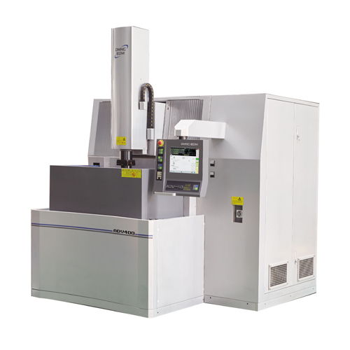
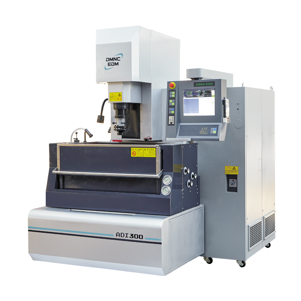
(1) The test device adopts the internal fluid channel processing device and the A2190 multi-axis simultaneous control CNC EDM die-sinking machine produced by the Beijing Institute of Electro-machining (BIEM) and Beijing Dimon Numerical Control Technology Co., Ltd (DMNC-EDM). (as shown in Figure 4). The main machine of the CNC EDM machine adopts a ram structure, the worktable is fixed, and the spindle head realizes movement in X and Y directions through the ram. The worktable bears a large load and the workpiece is installed with good stability, which can meet the test requirements. Table 1 is the main technical parameters of the A2190 machine tool.
(2) The tool electrode material is copper; the workpiece material is precipitation hardening corrosion-resistant stainless steel. Characteristic dimensions of the internal fluid passage: as shown in Figure 5, the outer end is an inclined hole with a ϕ25 depth of about 400mm and an inclined angle of 75°, and the inner end is an inclined hole with a ϕ15 depth of about 110mm and an inclined angle of 105°, which has been machined.


Main technical parameters of DMNC’s A2190 CNC die-sinking EDM machine | |
Item | Technical parameters |
Working table dimension | 2500×1200mm |
X, Y, Z travel | 2100×900×600mm |
The dimension of the working tank on the table(L×W×H) | 3310×1700×900mm |
Max weight of the electrode | 100kg |
Max weight of the workpiece | 7000kg |
Distance from the end of the spindle to the working table | 700-1300mm |

EDM machining selection parameters: in EDM die sinking machine, the polarity of the pulse power supply, pulse width, pulse interval, peak current, electrode discharge area, machining depth, electrode unilateral scaling, and other parameters and machining speed, surface roughness, Processing accuracy, electrode wear rate, and other processing effects are closely related and are important process parameters. The processing conditions are harsh, the processing position is deep, the tool electrode discharge area is small and irregularly changed, and the chip removal conditions are poor. In order to ensure stable processing, select a level of medium-precision process parameters for processing. This parameter must also meet the surface roughness. Requirements, the selection of EDM processing parameters are shown in Table 2. In addition, the two parameters of lifting height and lifting cycle are also very important, which can be adjusted appropriately according to the processing stability. The working fluid is DIC-302 special EDM fluid. The working fluid has low volatility, low odor, high flash point (>110°C), good safety, low viscosity, and good fluidity, which is conducive to chip removal processing.
(3) The test needs to complete the processing of the middle internal fluid channel about ϕ20 and the length of 87.3mm to realize the communication with the two oblique holes at the inner and outer ends. The coplanarity between the holes at both ends of the test sample and the internal fluid channel is ≤0.8mm, and the butt joint is smoothly transitioned, and the surface roughness Ra≤3.2μm.
2. Test results and analysis
After the machining is completed, use a CNC wire cutting machine to cut the internal fluid channel after the EDM machining, and then compare the processed section with the cross-sectional shape of the designed fluid channel three-dimensional model to check the processed size and shape; use surface roughness The standard template is compared with the processed surface quality to inspect the surface quality of the fluid channel after processing. Figure 6 is the overall photo after removing the test block from the workpiece, and Figure 7 is the cross-sectional photo of the removed test block, which can clearly see the shape of the connecting hole after processing. Figure 8 is a comparison photo of the surface roughness standard template and the surface quality of the processed part.


It can be seen from Figures 6 to 8 that the connection between the inner fluid channel in the middle and the two oblique holes at the inner and outer ends is realized, and the butt joint is smoothly transitioned; the flow channel after processing is basically the same as the fluid channel designed in Fig. 3, and the cross-section is in the shape of an oblong hole. The width of the fluid channel detected by the vernier caliper is 19.2~19.5mm, the coplanarity of the two ends of the test sample and the internal fluid channel is ≤0.8mm, and the surface roughness is obviously better than the machined surface. Compared with the surface roughness standard sample, Ra is 1.5 ~1.6µm, the processing result meets the design requirements.
Through the verification of the test method and analysis of the results, a preliminary conclusion obtained as follows:
1) The EDM flexible transmission device for internal fluid channels proposed in this paper and the developed bending avoidance structure, insulation and chip removal structure, and internal fluid channel EDM technology are one of the methods to realize the internal flow channel processing of such parts. An effective method.
(2) This device is feasible through actual machining verification. It can complete the EDM machining of the internal fluid channel with an angle greater than, equal to, or less than 90°. The diameter of the processed internal hole is 15-20mm; the two ends of the test sample and the internal fluid The channel coplanarity is ≤0.8mm, and the butt joint is smoothly transitioned; the surface roughness Ra≤3.2μm.
(3) It can be seen from the foregoing that the internal fluid channel cannot be achieved by mechanical processing methods. Using the characteristics of die-sinking EDM technology to solve the problem of mechanical milling and drilling that cannot be processed due to tool hardness, inaccessibility or interference is an effective way to solve this similar structure processing.
 Notes for maintenance of EDM small hole drilling machine
 The 2016 National EDM Machining Technology Seminar was successfully held in Beijing
 N85 5-axis Simultaneous Control Cnc Die Sinking Edm Machine Has Been Added Into “qualified Suppliers Catalog Of Domestic Made High Rank Cnc Machine Tools For Military Industry”
 GET STARTED